Future-Proof Your Devices With Phoenix Contact Modular Housing

From |

Housing is one of the key fundamentals for every household. Having the flexibility and availability of the right home will allow one to adjust comfortably when the family nucleus changes with time. Imagine a young couple that is planning for a family but is financially strapped and cannot afford a large home, obviously they will have to settle with a home that is smaller and more affordable. After a couple of years, their parents and children start to live with them. If they are more financially sound by then, the couple would need a place that is larger to accommodate a family of 7 people. The availability of homes in the market is key for the family of this size. 20 years down the road, the children would have grown up and moved out, and the family nucleus has strung back to just the couple living together. They will have the flexibility to downsize their home, or stay where they are currently residing.

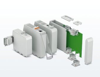
In the same way, any device will need a housing to encapsulate the PCB. PCB design changes with time and with the demands and needs of the market, the PCB can become larger or smaller. A suitable electronic housing will need to provide the flexibility to adjust to the needs of the PCB and components.

Phoenix Contact offers a wide range of housing for our customers. From DIN-rail mounted, desk or wall mounted, to outdoor applications and handheld types.

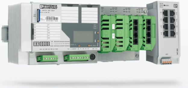
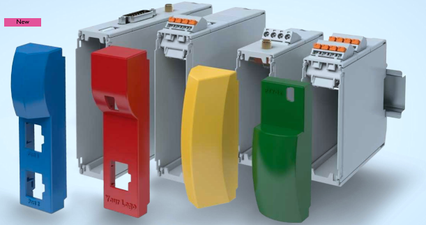
For this blog, we would like to touch on the latest addition to our electronic housing family, the modular ICS housing system mounted on the DIN-rail that is for future-oriented automation devices.

What is so special about this product compared to other housing products that are available in the market? How is Phoenix Contact ICS modular housing unique from rest in the market?

Let’s start from the beginning, from the R&D standpoint.

Say today the R&D team needs to redesign a din rail mounted controller to be integrated with their new machine, they need to come up with the concept and proof of concept within 2 months. With Phoenix Contact ICS modular housing, we can fulfil their needs, taking into consideration of their demands of:

  1. Tight timeline
  2. Unique design required with their company logo
  3. Reasonable cost

Phoenix Contact has an online configurator that allows the customer to configure and select the right housing for their needs. The available options for the R&D engineers in our online configurator would consist of:

  1. Size of the housing to fit the size of the PCB.
  2. Single or twin PCB allowed in the housing.
  3. Accessories options on the upper and lower side of the housing – such as connectors, heatsink & fillers with vent, USB, RJ45, D-sub or antenna.
  4. If customer has any customise cut out required, we can do it accordingly with our existing fillers.
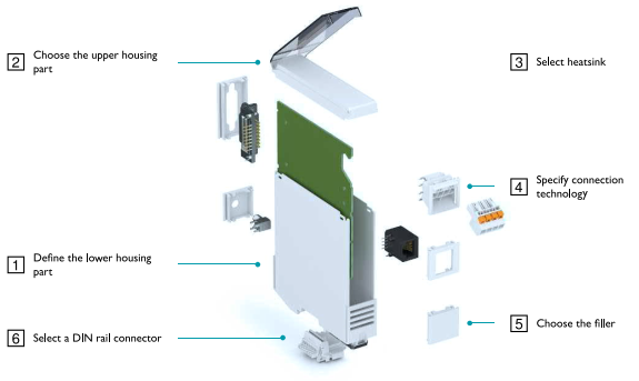
  1. T-bus connector available for the requirement of additional I/O modules.
  2. Front cover design options: Hinged transparent cover, flat closed cover or individualised custom cover. Customised printing and cut outs are also available for a nominal fee.
    No additional tooling charges involved!
  1. 3D simulation and CAD files available for download together with the part numbers of all selected parts and accessories.
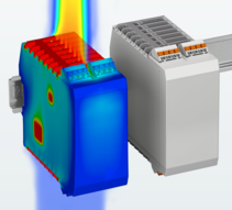
  2. Heat simulation available if used for IC or electronic components that generate lots of heat.
    While many other companies charge for the thermal simulation, these are all freely available online!

Only Phoenix Contact provide such extensive product offerings and services which translate to:

  1. Cost effectiveness – No tooling fee on a new housing design with the advantage of our semi-customisable housing and free thermal simulation.
  2. Unique housing designed by the customer – Custom housing with printing and individualised covers.
  3. Quick sample service – samples can be requested online or through an email to the local representative.
  4. Future-proof and full proof design – Engineers can switch to the same series of housing with different sizes for future designs and Phoenix Contact will constantly be adding more accessories and services to value-add to the customers.

After all the designs are completed, engineers will need to transfer the information to their purchasing team and prepare for mass production. From the online configurator, you can download the part numbers of every piece part in an excel spreadsheet. This will seamlessly translate the information from the R&D team to the purchaser with extensive information in terms of:

  1. Drawings
  2. Pricing
  3. Piece parts and manufacturing part numbers
  4. One supplier for the fully established housing requirements from material, printing, and customisation.

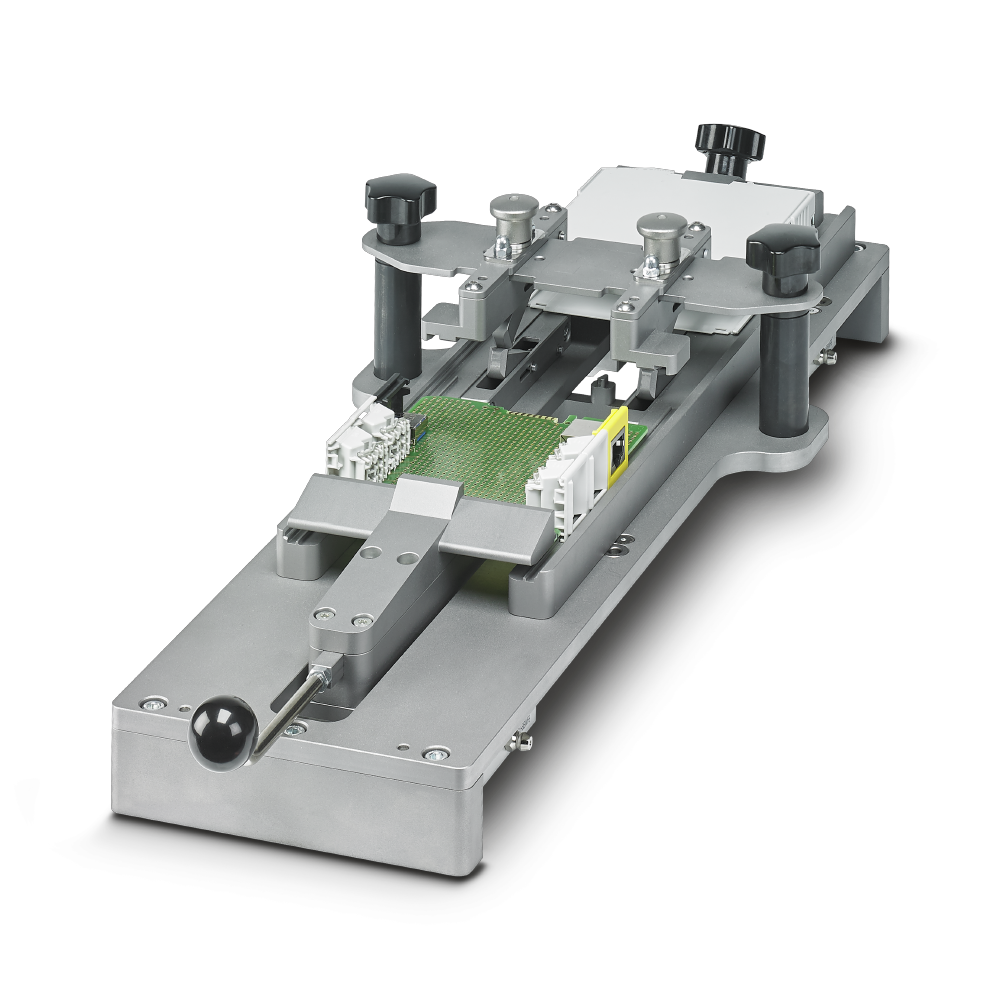
A well-thought-out product, the ease of the production process cannot be neglected. Phoenix Contact has designed a mounting device that is able to assemble all the different housing configurations, and shorten the assembly process to mere seconds. That is both innovation and cost saving. To find out more about the mounting device and the operation, see this link.

Reach out your local Phoenix Contact sales team to find out how we can help launch our new projects effective and efficiently.

Looking forward to hearing from you soon.

Contactron – Protection for Your Motor

From |

Everyone has tangible or intangible possessions that are close to our heart.

We will purchase insurance for our loved ones or get a mobile phone cover to protect our latest mobile equipment against impact. When the world was hit by COVID, we protect ourselves with masks and so on.

How do we protect our three-phase asynchronous motor from overloading and on and off switching procedures? Failure to protect these motors would result in downtime, production delays etc.

Phoenix Contact offers various CONTACTRON hybrid motor starters that combine up to four functions in one device:

CONTRACTRON also eliminates the usual way of wiring by integrating all the important functions into your safety chain.

We have various specifications to suit your motors’ needs.

Get in touch with us and we will provide the best protection for your motor needs.

Off Grid EV Charging for AC and DC

From |

Much has been said about “Decarbonization of Transportation” and to greener Electric Vehicles (EV).

But in a small country like Singapore, is it difficult to achieve such goals?

It is almost a monumental task to convert a certain percentage of our present Internal Combustion Engines (ICE) Vehicles to EVs.

Let’s do a comparison with a similarly populated European country that has successfully converted to EVs in the last 5 years.

Norway      Total Population – 5,421,241 as of 2020

Total Vehicle population – 2.8 Million of all types

When was EV Introduced in Norway?

In 2007, Oslo started the conversion to EV by installing 400 charging points from 2008-2011 in the City as a try-out for the switch to de-carbonization from ICE Vehicles. By 2011 it was deemed a success and that started the move away from Fossil Fuel transportation. It took them 13 years for this change to happen.

Singapore     Total Population –  5,690,000 as of 2020

Total Vehicle population of 973,990 of all types

Between the 2 countries the Energy Consumption in terms of Gigawatt/hour per Quarter estimates

Norway –   13.067 GW per Quarter

Singapore – 12.6 GW per Quarter.

Majority of Energy supplied in Norway is from Hydro-electric Plants (65%) Bio Gas (25%) and (10%) Solar, whereas in Singapore, it is mostly from Bio Diesel Generation (75%) and Solar (25%).

With the above statistics in mind, let’s look at the possible solutions for Clean Energy Generation for EV Vehicles.

This time we focus on Off Grid AC and DC Charging for less dependency on Fossil fuel generation and Renewable energy.

The system requirements for OFF Grid Charging

Here you have the basic Solutions block for an Off Grid System:

  1. PV Solutions that is connected to Main Switch board management system
  2. EVC – EV Chargers of AC or DC types
  3. BESS – Battery Energy Storage in DC (Lithium Ion or Vanadium Reflow Battery)
  4. Back End Controller to Gateway or for EV Charging Data
  • Optional connection to Grid as backup to charging the BESS should the PV system have insufficient supply of power to BESS.
  • Other loads to Motor or Pumps for infrastructure if the above is a micro grid system used in remote locations.

The above can be used with AC EV “Slow Chargers”, or if It’s connected to a bigger Solar Farm source that can connect to a 1.0MW -1.5 MW BESS to DC Fast Chargers of 60KW to 150KW.

OFF GRID AC Car Park Chargers Solutions

15/100KWh BESS connected to 2 AC chargers dispensing 7Kwh EV Charging Power

We have components for the following solutions:-

  1. EV charger solutions that can take 220VAC at 32 Amps Single phase to give 7Kwh AC charging. The Parking lot size caters for 2 AC Chargers.
  2. Power conversion rectifiers that can convert DC to AC from the BESS to AC EV Charger.
  3. Solar Combiner boxes from Phoenix Contact to Convert DC direct to BESS.

The solution can be connected to the back-end controller via Modbus and then to our Gateway for communication with backend.

OFF GRID DC Fast Charger Solutions

Solar Farm Generating 0.5mW connected to a BESS of 0.5MW to 1.5MW + 2 DC fast Chargers

Here in this DC Fast Charger solution, we have.

  1. Solar Combiners boxes to connect to BESS.
  2. BESS will have DC to DC rectifier blocks to stabilize the power output to the DC EV Chargers.
  3. Our DC Chargers will have all our “CHARX” products from HMIs to Charge controllers

DC to DC rectifiers to generate output power in DC at 60 -150Kw to EV Cars.

PLCnext – An Intern’s Perspective

From |

Many of you may be familiar with our next gen PLC called PLCnext, but how easy is it to actually make the switch? Today, I would like to share with you from a fresh perspective – that of a Phoenix Contact intern who has been learning to use PLCnext Technology for a mere two months.

As someone who has taken a few programming-related modules in university, I thought I had at least heard of most of the programming languages. However, when I first started learning about PLCnext, I was introduced to IEC 61131-3.

Credits to Marvel Studios

IEC 61131-3 is the standard for dealing with programmable logic controllers (PLC). The software used to configure PLCnext controllers, called PLCnext Engineer, mainly uses 3 PLC programming languages:

  • Function Block Diagram (FBD)
  • Ladder (LD)
  • Structured Text (ST)

Once again, I had never worked with any of these languages before in my programming modules. FBD was relatively easy to pick up, as the default function blocks in PLCnext Engineer provided more than enough functionalities for my internship project. The FBD editor was also extremely user-friendly. It also had the capability to change variables on the fly using Debug Mode, which made troubleshooting a real breeze.

A very beautified picture of FBD code

And yet, FBD was not a language I was familiar with. If you have learnt a new language before, you may have experienced times when you cannot express yourself or cannot translate your thoughts from your native language to the new language you are learning. Thankfully, that is where the prowess of PLCnext Technology comes in.

To make things short and sweet, PLCnext Technology essentially allows the use of different languages for programming of PLC logic. Instead of using IEC 61131-3 languages for the main program logic, languages such as C, C++, C# and MATLAB Simulink can be mapped to the IEC 61131-3 code. This is possible through a Global Data Space (GDS) which maps input and output ports of IEC 61131-3 languages with that of the other languages being used.

What this essentially means is that many people who are familiar with different programming languages can work on the same project! PLCnext Technology bridges this gap between programming languages, making automation that much easier.

That being said, some (extremely) basic knowledge of at least one of the IEC 61131-3 languages are required. However, this was easily picked up after I was loaned the AXC F 2152 Starter Kit to practice.

The AXC F 2152 Starter Kit

Two months into my internship, and I have already learnt enough to build a small-scale prototype of my final project. While I will not be delving into the details here, the important part is that majority of the logic is coded in C++, instead of IEC 61131-3 languages.

“This isn’t even my final form!”

If an intern can whip up something like this from scratch in two months, I am sure you can too!

PTV Lateral Push-in Technology

From |

Push-in Terminal blocks in vertical orientation?

Yes, I am sure most of us are aware of the easy-installation technology, called Push-in Technology. If you have never heard of it, please allow me to explain it with Phoenix Contact’s history.

Phoenix Contact was the first to develop modular terminal blocks. It actually started with screw terminal blocks and then gradually innovated with newer technologies.

Moving on from screw terminal blocks, we came up with spring-cage terminal blocks. Using the screwdriver, the spring-cage would be opened, allowing the user to install the conductor.

Compact ST spring-cage connection

And finally, we have Push-in technology which does not require you to get any tools to install rigid or ferrule fitted conductors. Yes, all you have to do is just slot the conductor into the hole and push it in, Voilà!

Again, with Phoenix Contact’s continuous innovation, we did not stop here. We now have lateral Push-in technology!

Instead of inserting the conductor from the top, now you can push it in from the side.

So, how does it benefit us more?

  • Best Ergonomics

Just like PT terminal blocks, you can connect rigid or ferrule fitted conductors directly without using any tools. Regardless of the listed conductor size you use, the contact spring ensures maximum contact and conductor pull-out forces with a vibration-resistant, gas-tight connection.

PTV, in fact, is best when it comes to a Fuse terminal block with push-in technology. If you are a user of this, you might have already faced this little situation. When you try to disconnect the fuse holder, the conductor might block you from flipping it over fully. With lateral Push-in technology, you have full freedom of flipping the fuse holder.

  • Best System compatibility

PTV, as a part of CLIPLINE complete, allows you to use the same set of accessories as other CLIPLINE complete terminal blocks with different connection technologies. The list of accessories for disconnect terminal blocks is:

  1. fuse plugs
  2. component connectors
  3. feed-through connectors, and
  4. isolating plugs

This versatility enables you to customize your switching devices.

  • Best Clarity

The conductors entering from the side will not bend and cover your markings on the terminal block. This also enables easier identification of conductor markings and connection.

Today, you can find the Push-in technology in various terminal block types from normal feed-through terminal blocks to even test disconnect terminal blocks. With our new lateral Push-in technology, we can offer you an even wider range of terminal blocks!

Plug & Play

From |

Vierarmen Tunnel – Belgium, is a 540 metres long tunnel which underwent a massive relighting project of more than 1,400 light modules. Advanced Automation was also implemented to enable remote operation and monitoring of the new LED tunnel lighting.

By replacing the old fluorescent and sodium lights with LEDs, the primary objective is to achieve energy savings. The longer service life of LED lights also means less maintenance is required, which translates to less holdups for road users.

Every effort was made to minimise inconvenience caused by the lighting replacement. The replacement work was completed in 45 nights per tunnel shaft, all thanks to the advance preparation and the simplicity of the plug-and-play system.

Good Collaboration

The replacement of the lighting in the Vierarmen Tunnel was carried out by the VSE – ENGIE Fabricom joint venture. Lighting systems from the Belgian manufacturer Schréder were selected.

Phoenix Contact supplied the Tunnel Control System and dealt with the implementation of the plug & play concept. Lastly, Tein Technology was the supplier of the central operating and monitoring system of the Flemish tunnels in the control room.

Every aspect of the installation was optimally coordinated to finally arrive at a reliable solution and to permit the installation of the system to occur smoothly and efficiently.

Minimum Energy and Maintenance

At the entrance to the tunnel, 300 candela per square metre is required. This entrance luminance is achieved by means of TAG lighting equipment.

Steven Hulpiau: “Because the light fittings can only be positioned on the side wall of the tunnel in this case, we are using special lenses that scatter the light beams to the side. In this way we can guarantee the required brightness everywhere in the tunnel with a minimum of energy. An additional saving arises from the fact that the lights can be dimmed.”

The electronics that control the lighting and that are normally located in the light fittings were in separate “driver boxes” installed right next to the light fittings. The advantage of this is that the light fittings do not have to be opened if maintenance needs to be performed on the electronics later.

Tunnel Control System

Tunnel Control System from Phoenix Contact is the beating heart, which consists of a controller, I/Os and communication modules that are used worldwide in tunnel projects.

The electronic control of the lighting makes a whole range of options and scenarios possible. To start with, there is the difference between daytime and night-time mode with lights that can be dimmed or switched off at night. The brightness control considers the sensors for measuring the luminance at both entrances to the tunnel. The aim is to guarantee sufficiently bright lighting with as little energy consumption as possible.

Plug & Play

For the new lighting installation to be carried out smoothly, various parties on the project collaborated on a plug & play concept.

Phoenix Contact’s QPD connectors were selected for the data network and the supply to the driver boxes and light fittings. Every cable in the tunnel project was custom prefabricated in advance, equipped with the required connectors and labelled.

The aim of this is not only to save time but also to increase the success rate during installation, which is, at its core, once more a matter of saving time. Compared with the traditional connection method, the use of the QPD connectors achieved a time saving of 75% during installation, and up to 15% of the total installation time in the tunnel.

Thanks to the seamless cooperation between the various parties and the consistent application of plug & play principles, the relighting project for the Vierarmen Tunnel was completed in a smooth and efficient manner. A sustainable, technologically high-quality solution was implemented with minimal inconvenience. Good lighting in tunnels is an essential aspect in guaranteeing the convenience and safety of road users.

3 Key Reasons Why a Managed Switch Is Required in a Network Topology

From |

Most of us should know that there are 2 main categories of network switches, the Unmanaged Switch & the Managed Switch. However, sometimes we struggle to understand when to use a managed switch.

In this article, we will look at 3 key reasons why a managed switch is required in a network topology. Hopefully, after this, you can make use of these 3 key reasons to identify when a managed switch should be used.

Reason 1 – Building network redundancy

Not every type of network topology provides a redundancy mechanism. And what that means is that they will often have a single point of failure – where if one network switch fails, it will stop the entire network from working. Some examples of network topology without redundancy include Bus, Star and Tree etc.

To provide more than a single point of failure, network topology with redundancy mechanisms such as the Ring, Mesh and Hybrid must be used. Managed Switches can support such network topologies through different network protocols. Examples of the protocols include Media Redundancy Protocol (MRP), Rapid Spanning Tree Protocol (RSTP), etc.

Reason 2 – Acquire and provide data for network diagnostics

As Lord Kelvin puts it, “To measure is to know. If you cannot measure it, you cannot improve it.” Similarly, we need to know the diagnostic data of our network topology, to understand its status and improve it.

A Managed Switch provides important information that can help us to monitor the network topology and call for maintenance before full failure of the system happens. This could be classified as predictive maintenance, which brings great reliability benefits.

Some key diagnostic information includes:

  • Port connection status 
  • Redundancy connection status
  • Power supply status (Interruptions)  

The acquisition of these information could also be achieved through different automation protocols such as MODBUS, Profinet, Ethernet/IP etc.

Reason 3 – Security features

Managed switches offer security features such as user-interface & port security.

A user-interface security prevents any unauthorised access into the switch management and configuration. While port security allows only devices with a registered MAC-address to send and receive data packets through the network switches.

Summary

There are many other applications of Managed Switches, such as the use of Layer 3 & VLAN applications, which are critical for big networks. In Phoenix Contact, we provide a good range of network switches for different applications that you might have. Find out more in the following link or contact us at Phoenix Contact SEA.

Phoenix Contact – Your “One-stop” Solution Supplier

From |

“Covid-19” – a common new term that the world has known since 2019. Many elevated sets of safe distancing measures have been widely adopted, with the movements of people being restricted in order to minimize the spread of the virus.  

Singapore was not spared from the paramedic.  The workforce in Singapore, where possible, had to work from home. Schools were closed, and the students moved to full home-based learning. Some businesses went into liquidation while others blossomed, particularly the online retailers.

Many of us changed the way we shop for our necessities or wants. For the heartlanders and neighborhood retailers, they brought their business online for contact-less transactions.

I am one of the strong supporters for online platforms, particularly those large e-marts , where it is like a one-stop solution shop where I can pick up all the necessary items in a single cart, instead of having to go around to different retailers to pick up one thing at a time in person. This saves me a lot of time, and petrol! Bringing more EFFICIENCY, which also means that I can use the same amount of time to get more work done. (I hope my boss sees this…)

This efficiency can be also be applied to the electronics design and manufacturing environment. One of the key fundamental elements to the success of a company, is managing the product costs. When you are taking longer than others to roll out a new design or when you’re not able to manage your material costs, it reduces the competitive edge that you may have. Time is of the essence.

Regardless if you are a Multi-National Corporations (MNC) or a Small Medium Enterprise (SME), the ability to turn around a new design and maintain a high production yield gives a higher efficiency and profitability level.

So, how can companies launch a new design in a shorter time and maintain a high production yield?

Let’s start from the basics.

Every electronic device consists of at least 1 printed circuit board (PCB). The PCB would be encased to avoid exposing the components which would risk damage or accidental electric shock to the user. Apart from the casement, most devices would come with some form of connectors, such as power plugs, communication ports or signal I/Os.

During the design of the device, there are many considerations to make; from choosing the suitable connectors and components, the placement of the connector(s), the light emitting diode (LED), ventilation openings for heat dissipation and many more. Lastly the engineer needs to choose a suitable enclosure or get a customized one.

Sounds like shopping for a “new house”? Pretty much…

Most components would often come from various suppliers and manufacturers. The designer would also need to coordinate with different parties to realize the device.

Being the designer, you would want to reduce this coordination work as much as possible and put the time to better use.

Phoenix Contact launched the first device enclosure portfolio back in the 1990s as a complementary product to the connector portfolio. Over the last decade, the portfolio has increased to not only include connectors, but other components such as heat sinks, keypads, light conductors and displays, making us a “One-Stop” solution supplier for devices.  

Apart from the wide product availability, the business unit has also built up competency to be able to offer strong development consultancy and services, such as thermal simulations, printing and customized cut-outs for our customers.

After the design is finalized, the next important aspect would be the manufacturing process. In many manufacturing processes, the standard enclosure would be sent to a 3rd party for printing or opening of cut-outs for the LEDs or the field connectivity ports.

During this manufacturing process, it could result in damage of the electronic housing. This loss manifests itself as assembly scrap, which can result from breakage, poor quality, or nonconformance to specifications.

Meaning to say, you may place an order of 100 sets of the device and only 97 sets come back from the milling process that conforms to the finished product specifications, and this varies from time to time. Maybe you do get 100 sets in return, but at a higher cost. 

Sounds too complicated?

Phoenix Contact is able to implement a customized enclosure solution coupled with connectors which will be delivered to you according to your specifications.  We will also walk the journey with you providing complete support and cooperation throughout the new device development process until market release.

Reach out to the local Phoenix Contact sales team to find out how we can help you launch your new designs faster, with increase your yield of production with our enclosure and connector solution.

Now, we have the time for coffee together.

Power Reliability for the ‘New Normal’

From |

With the backdrop of COVID-19, the new reality taking shape is made of complexity, uncertainty and opportunities. Industries are rapidly adjusting, and as the crisis unfolds, it is important for us to adapt to the new ways of business and life in this ‘new normal’.

The 4th Industrial revolution has picked up its pace, with the pandemic highlighting the role of technology, such as the Internet of Things, artificial intelligence, robotics and big data. To adapt and thrive, automation industries must accelerate and transform with more resilient, reliable and agile power solutions.

In Phoenix Contact, we have a comprehensive range of technologically leading products, ensuring your system and machine power reliability.

SPDs with effective power surge protection
Market leading power supplies for superior system availability
Device Circuit Breakers protect system devices from fault current

True power reliability is putting together the technologically leading products, with specialized, well-coordinated features and meeting customer application needs in 4 main key different aspects.

Continuous Power – Market leading power supplies solutions to safeguard control system with seamless operation. Examples include AC & DC Uninterruptible power supplies (UPS), battery-less UPS, and redundancy power.

DC & AC Uninterruptible Power Supplies / Redundancy Power Supplies

Robust Protection – The power solution works reliably in harsh operating environments. For example, during electrical power surges & over-currents, mechanical shocks, vibrations, extreme climatic temperatures and dusty operating conditions.

Power SPDs / IP67 Power Supplies / Device Circuit Breakers

Energy Efficient – Reliable products featured with high MTBF, long lifetime expectancy, energy savings and are environmentally friendly.

Intelligent Monitoring – Market-leading innovative products, enabling the smart connected power solution with preventive, predictive info.

Surge Monitoring-Impulsecheck / UPS – Intelligent IQ / Device Circuit Breaker (IO-link)

We aim and strive to help our customers to embrace the ‘new normal’ for their systems, and ensure their machines’ maximum availability.

Contact us now. Your trusted partner for reliable power.

Signal Conditioners

From |

At Phoenix Contact, there is always a signal conditioner for any application, such as filtering, converting, isolating and amplifying.

Amplifying
Converting
Filtering

The portfolio also comprises of solutions for interference free signal transfer in the areas of functional safety or explosion protection.

Industries such as plant engineering, power utility and process technology will require more process signals compared in the past. This is due to process optimization or energy savings. The need for more signals will be required and space is also a factor for consideration.

These optimized signals will go directly into the controller. Phoenix Contact’s Mini Analog Pro’s width is only 6.2mm, which makes it suitable to be installed in confined spaces.

The design makes the access points highly visible and allows simple connection of wires, therefore, saving lots of time and money.

FASTCON Pro interchangeable terminals are pluggable connection terminal blocks that are available in push in or screw technology. It is also integrated with measuring points, allowing measuring of analog signals during operation without the hassle of disconnection in the circuit.

Built in Dip switches, software solution or the app function enables easy access to information. Remote configuration can be done via PC or smartphones with Bluetooth or NFC functions.

Easy and detachable gateways with plug and play solution can integrate up to 8 field signals directly into digital communication protocols and into controller level. This removes the costs and trouble of use of signal specific cards, the risk of wiring error and high space requirements in the control cabinets.