Tag Archives: Safety

Safety in Tunnel Applications

From |

Commuting each morning via the 12km road tunnel during peak hours, it only takes a little more than 15 minutes to reach my destination from home. It is difficult to imagine thousands of cars passing through each day without hearing many accidents being reported on the news. However, when calamity arises, it is then clear that the safety systems have been put in place, ensuring the safety of road users at all times.

Have you ever wondered what is going on behind the scenes?

The road tunnels are designed in accordance with directives which specifying the minimum safety requirements. Aside from the emergency exits and emergency telephones available at regular intervals, it is paramount that the tunnels must always be supplied with power, light, fresh air and water for firefighting.
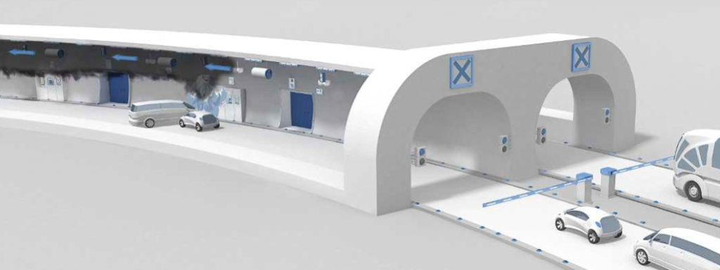
Take the ventilation system for example. It helps to remove toxic gases when the NOx, CO or CO2 levels are detected to be high during normal operations. In the case of a fire, the operator depends on the same system to purge the smoke and heat from the tunnel, away from motorists evacuating the tunnel or the emergency response team that is tackling the disaster.

To minimise potential casualties, Phoenix Contact has developed the Dynamic Evacuation Guidance (D.E.G). The automated D.E.G comprises of a full redundant configuration, where the guiding handrail is monitored by a pair of redundant PLC to guarantee maximum availability. Together with its 2-hour phosphorescence effect on the guiding handrail, the worst-case scenario during a loss of electrical power is also mitigated.

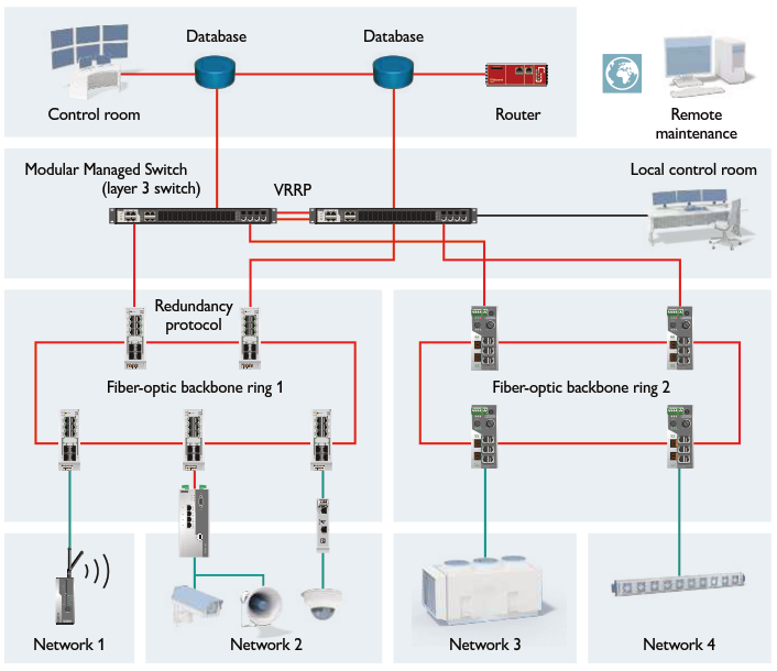
It is equally important to note that all state-of-the-art safety systems will not be operating at its best without a reliable communication network. The integrated backbone communication network is typically setup in several redundancy levels. At “switching level”, the entire tunnels are segregated into various “zones” covering certain sections of the tunnel. These “zones” are then grouped together through the “routing level”. With this structure, network failure (should it ever occur) can be isolated, without affecting other parts of the communication network.
Safety Valve Interlocking System

From |

The Problem:

In a chemical process plant, emergency situations can be extremely costly, both in terms of equipment and human life. However, under such extreme circumstances, it is rare that operators are able to effectively shut down all of the valves and pumps in the process line.

The Task:

We were given two weeks to install an upgrade to their existing system, along with the programming. The idea was simple – interlock the whole system so that no matter which part of the line the operator was, he/she would be able to shut down the entire system from his/her location.

The Solution:

Human-Machine Interface (HMI)

Human-Machine Interface (HMI)

We integrated Phoenix Contact’s Smart PLC Logic Relay and Human Machine Interface (HMI) into their system, splitting all of their valves and pumps in the process line into three zones. In the event of an emergency situation, the operator need only trigger the relay in one zone to shut down the whole process line.

Why it’s awesome:

Instead of having to run to separate parts of the process line to shut them down individually (and quite possibly realising how much more they need to train their running stamina and cardio over the weekends), all the operators have to do is to trigger the nearest zone. This not only saves time and effort, but more importantly equipment repair costs and human lives. This one-touch-kill-switch also reduces the risk of the operator forgetting to shut down some of the more remote areas of the process line in the heat of the moment, which would undoubtedly lead to higher repair costs.

In addition, our solution boasts the following features:

  • Easy troubleshooting on HMI with clear indication of which zone the emergency button was activated.
  • Easy maintenance work with interchangeable plug-in elements.
  • Reduced risk of system failure.
  • Allows greater flexibility for future system modifications.
  • Traceable data logging of system information.

Interested to find out more? Feel free to contact us!

Why Use Safety Relays?

From |

Let’s say you are asked to be a Design Engineer for a day and are tasked to come up with a Process Control Safety System. What are the questions you should ask? 

  • What happens to the Safety Instrumented Systems (SIS) when the relay contact is welded?
  • When did it happen?
  • Where can you find this faulty relay?
  • Why did this happen?
  • Who will be responsible for monitoring this fault?

Safety Relays are devices that implement safety functions. In the event of a hazard, a safety relay must work to reduce risk to an acceptable level. The safety relay must initiate a safe and reliable response as well as monitor the integrity of its function.

The Process Automation Fire & Gas System is always on standby mode and it becomes more important to have multiple diagnostics to make sure the relays used in the Fire and Gas System Safety remain functional with all wiring connected.

7 Functions the ideal safety relay should have for Fire & Gas Systems:

  1. Power loss diagnostics to field devices such as the Beacons, Solenoid Valves and Fire Sounders.
  2. Field devices disconnection diagnostics.
  3. Alerts when Field Devices short circuit.
  4. Welded relay contacts diagnostics.
  5. Able to Proof Test relay points without the use of external power.
  6. Diagnostics via the same cable to the relay coil by the use of test pulse filtering. This also saves money as there is no need for additional DI cards and cables for monitoring function.
  7. Option for redundant connection to the relay coil.

Safety Relay Connections

Safety Relay Connections

PSR-PC50 Series SIL Coupling Relay

PSR-PC50 Series SIL Coupling Relay

The Phoenix Contact PSR-PC50 series SIL Coupling Relay has the 7 functions you are looking for and it can also be used for power adaptation and electrical isolation in Safe-State-ON applications up to SIL 3 according to IEC 61508 as well as IEC 61511.

This category 3 device is designed for installation in zone 2 potentially explosive areas. By filtering the controller test pulses, premature failure of the safety relays is prevented. The contact side is fully monitored for open circuits and short circuits as well as load and diagnostics supply voltage. If an error occurs, the internal device input impedance is affected. As such, the test pulses sent from the controller are disrupted and the error is reported to the corresponding digital output without additional wiring effort.

If you have any questions or want to know more about this product, please feel free to send us an enquiry at marketing@phoenixcontact.com.sg and a product representation can be arranged to discuss in more detail.

Safety is by Choice, Not by Chance.

From |

Phoenix Contact's Safety RelaysAre you selecting a safety relay just to meet the SIL3 requirements?

Who will be responsible for conducting the Proof Test to ensure it is still safety relays are still safe to use?

Which is critical? Safety relays without diagnostics or the Safety relays with diagnostics?

Safety is a Choice, Not by Chance

The graphics below explains the functional principle of the force guided /positive driven contacts in the event of a welded contacts and that’s where the normally closed contacts come into action to provide feedback to inform the system of the failure in relay contacts.

In this case when the relay is de-energized, the normally closed contact cannot close properly having a gap of 0.5mm.

Animation of how Force-guided relays work

Click the image to see the animation of how Force-guided relays work

Safety relays for ESD-Emergency Shut-Down Systems should have:

1) Force guided relay enables a feedback path just in case of welded contacts and eliminates the need for simplifies Proof Testing. (ESD-Emergency Shut Down and F&G-Fire & Gas systems)

Emergency Shut Down System Circuit

Emergency Shut Down System Circuit

Safety relays for F&G-Fire & Gas Systems should have:

The diagram below shows connection details for a safety relay used by Fire & Gas Systems. The Fire & Gas System is always on standby mode and it becomes more important to have multiple diagnostics to make sure the Fire and Gas System Safety Relay is still functional and all wirings are connected.

Fire & Gas System

Fire & Gas System

  1. Diagnostics for lost power input to field devices: Beacons, Solenoid Valves, Fire Alarm Bell.
  2. Field devices disconnection diagnostics.
  3. Short circuit field device diagnostics.
  4. Diagnostics for any welded contacts.
  5. Proof Test points (TP1, TP2, TP3) without the use of external power.
  6. All diagnostics via the same cable (A1,A2) by the use of test pulse filtering.
  7. Option for redundant connection (A1’, A2’).

If you have sales enquires to know more about this product, please feel free to send us an enquiry at marketing@phoenixcontact.com.sg and a sales visit can be arranged to discuss in more detail.