The choice of the right connection technology is crucial for seamless processes in automation and digitalization. Reliable data transmission is essential, and selecting high-quality components is paramount. Low-cost options often lead to errors and costly repairs. Phoenix Contact offers specialized RJ45 patch cables for different application areas, ensuring reliable data transmission and compliance with required properties. Choose the right components for optimal efficiency and value in operations.
Ensuring Reliable Data Transmission for Efficient Processes
Automation, digitalization, and Industry 4.0 rely on consistent data acquisition and transmission. The choice of the transmission medium is critical for reliable data processing and control. Increasing data volumes require effective collection and analysis. Sensors generate data, while actuators utilize it to control systems. Selecting the right transmission medium is essential for seamless data transfer.
The wrong choice weighs heavily
Proper component selection is crucial for seamless data transmission. Choosing low-cost, low-quality options can lead to errors and costly repairs. Copper is commonly used as a transmission medium, but caution is needed to avoid unreliable products. Selecting high-quality cables designed for specific applications is essential for smooth processes and successful operations.
Choosing the right component
Phoenix Contact offers a clear portfolio of RJ45 patch cables for different application areas. The top line is the RJ45 Industrial patch cable, designed for demanding industrial environments. It features robust connectors, mechanical stability, 360° shielding, and the trustworthy transfer of data. for various protocols and speeds. They also offer variants for less demanding applications, ensuring reliable transmission while meeting specific requirements.
Fighting the climate crisis with series production
Power-to-X is a vital part of the energy revolution, aiming to replace fossil fuels with renewable sources. It involves converting renewable electricity into gases, chemicals, or fuels. PtG methods, particularly important for sector coupling, utilize existing gas infrastructure for storage and transport. The “European Hydrogen Backbone” envisions repurposing and expanding the infrastructure for hydrogen transportation. Automation and electrification strategies, such as Enapter AG’s AEM electrolyzers, are crucial for cost-effective and safe conversion processes. The installation of more wind and solar systems will further drive the transition to cleaner energy.
Interconnection of numerous electrolyzers to create gigawatt plants
Germany is witnessing an increase in PtG plants, using various electrolysis methods and reaching several megawatts of power. Plans for 100 MW plants are underway in Lower Saxony. Projects in Neom and Rotterdam will utilize gigawatt-scale electrolyzers. Germany aims to create 10 GW of electrolysis capacity by 2030. Green hydrogen is converted back using fuel cells or chemically into substances like ammonia or methanol. Automation and communication strategies are crucial for all processes, from hydrogen generation to consumption.
Manufacturing containers based on the industrial model
Manufacturers are developing containerized electrolyzers for hydrogen production, allowing for modular and interconnected gigawatt-scale plants. Industrial manufacturing methods enable efficient mass production of these containers. Providers like Phoenix Contact offer connection and automation technology, assisting with component selection and providing engineering and design services. Enapter AG’s AEM Multicore electrolyzer system uses an ion-conducting membrane and a cheaper catalyst, allowing for cost-effective hydrogen production with renewable electricity.
Supply of ready-to-use control cabinets based on PLCnext Technology
Enapter’s scalable AEM Multicore solution consists of interconnected stack modules in a container, producing up to 450 kg of hydrogen per day. Phoenix Contact provides control technology and DC power supply for the electrolysis stacks, including ready-to-use control cabinets. The container control room monitors hydrogen production, tank levels, and safety measures. Phoenix Contact’s PLCnext Technology handles control tasks and supports maintenance concepts. The control cabinets incorporate Ex protection components for hazardous areas.
Implementation of safety-related applications up to SIL 3
Phoenix Contact’s automation solution allows for safety-related applications up to SIL 3 in electrolysis plants. They offer cost-effective options, such as extending the PLCnext Control with an SIL 3 module. Their safety portfolio includes power supply units, relays, and motor starters. Comprehensive solutions for DC power electronics, like Charx Power modules, are available. The use of electrical connectors improves assembly efficiency and reduces costs. Phoenix Contact provides a wide range of products to support the scaling of hydrogen production in Germany.
Consultation in all phases of the lifecycle
Phoenix Contact offers consultation services for various aspects of plant development. They help determine cooling capacity, assess safety integrity levels, and provide assistance with technical specifications, safety software implementation, and testing. Their consulting service covers control cabinet building, including CE marking, EMC, explosion protection, and access protection.
Communication solutions in all directions
Phoenix Contact supports communication and integration in power-to-X applications. They assist with the dynamic operation and functional integration of electrolyzers with power generation and consumption areas. They provide solutions for fuel cells as emergency power systems and offer support for remote control, maintenance, data collection, and digital twin implementation. Their portfolio includes products for reliable and secure data transmission. Phoenix Contact’s certified products ensure IT security. They are also developing software modules for future use, enabling newcomers to create their own software applications in the power-to-X industry.
MTP as the basis for modular solutions
Phoenix Contact supports the implementation of large modular electrolysis plants for green hydrogen production. They facilitate scalability and reduce implementation effort through the use of standardized MTP (Module Type Packages) interfaces, allowing for modular automation solutions.
Find out more about the new standards on our website.
Marmo NV, a meat processing company in Belgium, focused on energy efficiency when renovating its refrigeration system. They partnered with Sabcobel, an experienced cooling systems company, who chose Phoenix Contact’s speed starters for fan speed regulation. The renovated system utilized CO2 as the evaporating refrigerant minimized refrigerant quantity and repurposed residual heat for hot water generation. Sabcobel’s expertise in creating cold chains for the food industry ensured a successful installation at Marmo.
Compact design saves space in control cabinets
Marmo has 60 chillers in their production area, each with a specific setpoint controlled by a system. Phoenix Contact’s speed starters regulate the three-phase AC fans’ speed, ensuring employee comfort and consistent temperatures. The system includes an air boost function in each room, allowing employees to increase air speed when needed. This flexible fan speed control system prioritizes energy efficiency while enhancing comfort. The compact design of the speed starters was a key factor in their selection, as they require minimal space in the control cabinet. These modules offer functionalities that bridge the gap between motor starters and frequency converters, operating on three-phase power with a maximum power rating of 1.5 kilowatts.
Flexible I/O system for connecting the chillers to the central PLC
The refrigeration system at Marmo is efficiently controlled by a central PLC unit connected to distributed I/O islands through the Profinet protocol. This setup offers cost savings and improved efficiency.
The system includes 11 distributors responsible for controlling the 60 chillers in various rooms. These distributors are connected to the central PLC using the Profinet network. To manage the I/O islands effectively, Marmo opted for the Axioline Smart Elements I/O system from Phoenix Contact. This choice was driven by the system’s compact design and flexibility. The installation incorporates a significant number of digital and analog inputs and outputs, including RTD cards for temperature sensors, pressure measurement, and gas detection. The use of Smart Elements modules on a backplane enables seamless communication via Profinet network.
furthermore, one notable advantage of the distributed I/O system is its transparency to the central PLC. This simplifies the management and monitoring process for the system, making it easier to control and maintain.
Remote monitoring for in-service support
Implementing the new refrigeration system during production was a challenge, but the user-friendly Smart Elements modules with Phoenix Contact’s tool-free Push-in connection technology proved beneficial. Also, Maintenance Manager Tim Steegmans appreciated Sabcobel’s support and the system’s industrial approach for operational reliability. Remote monitoring and remote reset capabilities in speed starters enabled efficient assistance from Sabcobel’s specialists.
Find out more about the new standards on our webpage.
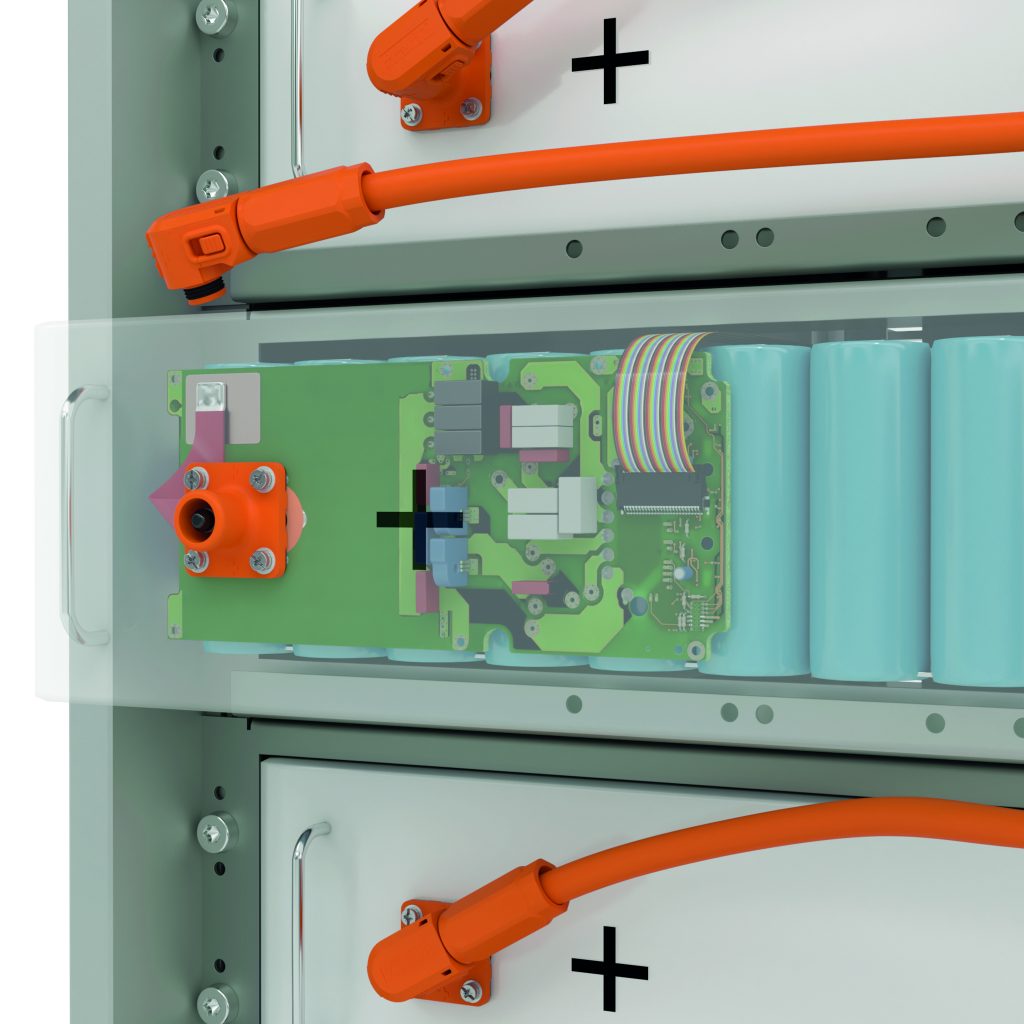
Energy storage systems are key to an All Electric Society. Ensuring a stable energy supply by compensating for the volatility of renewable energy sources. This report looks at the typical design of a battery system storage system. Furthermore, exploring the flow of energy and information between the various components. Discover how electrical connection technology can ensure reliable storage systems and support a successful transition to an All Electric Society.
Typical energy storage system design
Electric energy storage systems based on galvanic batteries can be applied to a variety of sizes, from multi-megawatt-hour systems to small home systems of 10 kilowatt-hours. Battery cells are connected in parallel or series to form packs, and welding technologies are used to create permanent electrical connections. This modular design is adjustable and has only a few limitations.
The battery module
Storage modules house large numbers of cells and are monitored and controlled by a Battery Management System. The BMS measures and sets the voltage and current of cell groups for uniform charging/discharging (balancing), and provides power and data connections from the BMS PCBs to the module housing (usually with screw connections for power and plug-in concept for data).
Industrial 5G, the next generation of wireless technology, will provide reliable, high-speed, and low-latency connections for a large number of users. This will enable flexible, autonomous, and efficient processes from production to logistics in the future.
What exactly is Industrial 5G?
5G is the latest cellular standard offering high bandwidth, real-time capability, high reliability, security, and support for large numbers of users.
Basically, 5G is the first cellular generation to satisfy industrial sector demands, enabling intelligent wireless communication between machines and applications. Besides, enables private networks for flexible, sustainable network connections in mobile or highly flexible applications.
Industrial 5G is the perfect technology for Industry 4.0. It provides high levels of flexibility, usability, and efficiency that will enable smart factories and the IIoT.
5G technology’s features and characteristics
Industrial 5G provides higher performance than earlier cellular standards, with features like low latency (ultra-reliable low-latency communication, URLLC), high connection density (massive machine type communication, mMTC), and bandwidth (enhanced mobile broadband, eMBB), as well as comprehensive IIoT connectivity and greater flexibility.
Industrial 5G enables customized properties to be assigned to each application, granting specific resources in a private network. This provides a triangle of functions, delivering enhanced flexibility and control.
In the future, it will be possible to create consistent private 5G networks for specific applications. These applications will replace the current mix of wireless and wired technologies (e.g. WLAN, WirelessHART, GSM, LTE).
It is more crucial than ever for businesses to measure and analyze loads due to increased energy costs and strict legal obligations. Now, it is possible to complete this operation with IoT solutions that are simple to deploy with Plug and Play and accessible by IIoT platform and need for very little prior knowledge. Two instances from the production sector show how businesses might profit from this.
Prior to now, the energy consumption data that was included in the daily machine data had a minor function. That changed at the latest when the CO2 footprint became a significant KPI and energy costs increased significantly with less notice. All sectors that use more energy must now make the pertinent parameters measurable and analyze-able and show a continuous improvement in energy-related performance. Greater data transparency will be beneficial, particularly for small and medium-sized businesses (SMEs) that have up to now either utilized no energy monitoring at all or only very basic energy monitoring.
One reason is that companies can more easily comply with regulations and legislation and have a more thorough picture of how much energy certain machines, processes, or systems are using. They discover savings possibilities with the aid of this data, which in turn can help to raise energy efficiency and lower energy expenses.
Obstacles
However, finding a quick and accurate way to gather the essential consumption data is a challenge for those in charge of managing energy in businesses. For instance, smart meters installed on equipment and systems can often link to the IT infrastructure using communication protocols. Hence, they require more storage capacity, lengthy Excel lists, or appropriate analytics tools that, in the best-case scenario, may also assist with useful visualization. In other words, up until now, it took time and a lot of knowledge to connect various devices, record and analyze the necessary data, and then draw ingenious inferences from the findings. For energy managers, who frequently must work across numerous sites and with limited resources, this presents a significant issue.
Plug and Play connection to the cloud IIoT platform
This situation appears to have been created specifically for an IoT-based energy management system. Minimal IT resources can implement this kind of solution. Utilizing IoT-enabled measurement devices in the relevant control cabinet or at the machine/system, connecting them to a router, and creating an account with a cloud service are requirements. One such is the coupling of Phoenix Contact’s IoT-enabled EMpro energy measuring devices and the EMMA Service of the Proficloud.io IIoT platform. Energy Monitoring, Management, and Analytics is the abbreviation for EMMA. The smart service’s user-friendly interface makes it easy to visualize linked devices’ electrical energy and performance information. Regardless of where you situate the measuring devices, energy managers may access their data using this cloud-based system. The knowledge gained in this way permits the definition and use of appropriate measures.
The EMMA Service supports energy managers here in the check step of the PDCA (Plan, Do, Check, Act) cycle in accordance with international standard ISO 50001:2018 (Energy management systems – Requirements with guidance for use)
IoT-capable Through an Ethernet interface and Plug & Play using the TLS-encrypted MQTT protocol, EMpro energy measurement devices are immediately connected to the Proficloud.io IIoT platform. Energy managers may quickly and easily integrate the measurement devices into a new or current system using the free Device Management Service in the cloud environment. Automatically send and save the chosen measured devices. Energy managers now have access to this data and can use them directly thanks to the EMMA Service. Modbus or Profinet’s intricate settings, which were once common in industrial networks, are now a thing of the past.
Additional advantages of continuous energy data acquisition
Operational energy management is based on the continuously gathered energy consumption data of equipment, systems, and processes. They also offer the following further benefits:
Optimize system utilization via intelligent component switching, balanced network loads, and the removal of harmonics.
Smart trend calculations and load control can lower peak loads.
Consistently monitor system parameters to reduce system downtimes.
Example applications from industry
Two examples explaining the EMMA Service functions:
Cold storage
Snack producer A aims to achieve CO2-neutral manufacturing and sustainably reduce energy costs, thus it would like to be able to see how much energy is used during cold storage and production. The company needs to be aware of two aspects in to determine the necessary energy efficiency measures and the procedures to reduce energy consumption: Let’s start with how much energy is now needed to cool a ton of potatoes that are kept in a cold storage facility. Second, it is also curious about how much energy is used to produce each kilogram of the goods it produces. The prior monthly meter read-out and Excel lists used to evaluate it took a lot of time and didn’t provide the transparency needed to meet A’s two objectives.
IoT-capable EMpro energy measurement devices now make possible the straightforward and comprehensive documentation of the energy data and the EMMA Service. The company enhanced its cooling based on the quantity of potatoes stored and streamlined the production process based on the knowledge gained. As a result of their connection to Proficloud.io, the energy management team has access to the worldwide sites and their energy data.
Bottling of beverages
Beverage company B has set a global goal reducing CO2 carbon emissions by 25% for the entire group. The first essential step to reaching this goal is to monitor and carefully control how much electricity, water, heat, and compressed the company is using. The beverage manufacturer deployed the necessary measuring equipment at the indicated primary loads for this reason, and Proficloud.io receives the measured data directly. The dashboard now allows the energy managers at B to quickly and easily visualize and analyze the loads there in real time. The goal of the firm leaders in the US is to prioritize providing comprehensive information on local, location-specific dashboards while also displaying the total energy consumption of all the Group’s energy sources on a worldwide dashboard.
This is exactly what the EMMA Service on the Proficloud.io IIoT platform can do. Proficloud.io also provides the opportunity to control the rights and duties of the employees inside a company using the User Management Service. Additionally useful is Proficloud.io’s Time Series Data Service, which analyzes extra data using freely customizable dashboards.
Access to newly implemented functions
Phoenix Contact, a full-service supplier in both cases, offers the hardware elements needed to connect to the cloud, including controllers, gateways, and energy-monitoring gadgets. The Proficloud.io IIoT platform and its standardized, scalable smart services, one of which is the EMMA Service, are accessible to the IoT-capable energy measuring devices in the EMpro product family. Phoenix Contact focuses on best-practice solutions that are simple to use, constantly evolve to meet client needs, and are based on the needs of regular business operations with its smart services. In conversations with users, new features and quick problem fixes frequently emerge. They also see the benefit of cloud-based services in general: As soon as newly added features and performance characteristics are available, existing users get direct access to them.
The energy revolution will significantly impact future electrical power generation and distribution since it is rapidly bringing about an All-Electric Society (AES).
Economical electrical energy produced from renewable resources, Is the primary energy source In the All-Electric Society, is which is almost inexhaustible. Comprehensive electrification, networking, and automation of all facets of the economy and infrastructure are necessary to make this future a reality.
This involves a more significant usage of non-linear or switched power producers and loads and an increasing decentralization of power generation using renewable energy sources for our power systems.
Restrict the harmonic loads and feed-ins in the transmission and distribution grid when they become more viable. This will include, among other things, an increase in measuring and safety equipment usage.
Creating more measurement points and the digital networking of signals from switchgear and substations in power distribution control systems need the conversion and modernization of current systems.
Here, measuring transducers convert high currents and voltages to quantifiable variables to acquire the measured values in the switchgear.
Terminal Blocks
Test-disconnect terminal blocks serve as the link between higher-level evaluation units, such as metering or grid protection relays, and the measured-value acquisition performed by current and voltage transformers. As part of cyclic function testing, these disconnect terminal blocks allow for direct involvement in the program.
Here, safe handling is essential, made possible by the extensive touch protection in current test-disconnect terminal blocks. These terminal blocks offer a variety of test and switching accessories in addition to the disconnect element for secure, adaptable, and practical testing.
Older systems frequently have terminal blocks with switching accessories with basic or limited touch protection. Connect the testing sockets to the non-insulated test plugs to accomodate non separating switching parts. The widely used and well-tested screw connection method has included the conductor connection. Connect the testing sockets to the non-insulated test plugs to accomodate non separating switching parts.
Meanwhile, this area has shown to have enormous potential for future growth. Modern terminal strips contain extensive, standardized accessories like the CLIPLINE complete system and the possibility of conductor connection using quick and straightforward Push-in connection technology.
Quick and easy: Conductor connection with PTV
Push-in vertical
From a physical standpoint, screw connection terminal blocks have a long history and offer certain benefits over spring-cage terminal blocks. For instance, a screw connection allows several conductor connections at a single terminal point without requiring conductor pretreatment.
However, when it comes to upgrading systems, a spring-cage connection is becoming more and more popular.
One typical explanation for this is the frequent recommendation of routine inspections for screw connections to confirm the conductor’s torque-secure connection.
Phoenix Contact secures the screw connections by providing screw terminal blocks with built-in screw-locking mechanisms and eliminates the need for further checks
However, the aforementioned restrictions do not consider the specific items applied to screw connections.
The PTV terminal block, created by Phoenix Contact, is a unique replacement for screw connection terminal blocks.
PTV, short for “Push-in vertical,” is a connection method that uses the standard Push-in connection technology. The primary distinction is in the conductor routing, which is vertical and resembles a traditional screw connection as opposed to the front wiring of Push-in connection technology.
One notable benefit is that, unlike Push-in connection technology in the past, the terminal marking is clearly visible and not covered by the conductor routing. In addition, the lateral conductor connection offers advantages during the redesign if cables are permanently fixed in existing control cabinets and cannot be removed. Maintain additional cable length in reserve to alter the front wiring of the control cabinet. Utilize the cable length if the conductor routing changes.
PTV is the contemporary version of a screw connection; however, unlike a screw connection, it does not call for regular tightness checks.
Thus, the PTV test-disconnect terminal blocks combine the benefits of a spring-loaded conductor connection with those of a screw terminal block.
Compact design
The control cabinet architecture is still crucial when replacing test-disconnect terminal blocks in existing systems since they cannot visibly outweigh the old ones in terms of length or breadth. Due to their small dimensions, the new PTVME test-disconnect terminal blocks with vertical Push-in connections may be fitted in the location formerly held by the outdated screw connection terminal blocks.
The lateral conductor connection may still be made because of how small the terminal block is; even the clearly visible connection identifier is still placed above the conductor entrance.
Comprehensive accessories
The screwless longitudinal disconnect element on the PTVME 6/S test-disconnect terminal blocks may be adjusted to the correct switch position with a screwdriver and locked into place.
Secure an auxiliary lever to manually control the disconnect element. The printed switch symbols indicate the switch locations. Utilize the switching locks on either side of the disconnect point to avoid unintentional activation.
On either side of the disconnect point are universal double-function shafts that let you utilize different bridge, test, and switching accessories.
When retrofitting systems, practical design and setup of terminal strips are crucial since they may quickly restore availability.
Push-in spring connection technology makes wiring quicker. The documentation and planning of terminal strips can take a significant amount of time. Clipx ENGINEER is a free planning and configuration tool by Phoenix Contact used from the CAE design stage to installation
Transport is fundamental and It is crucial to take steps to make it sustainable. The mobility of the future, therefore, depends on the world adopting electric vehicles that do not emit greenhouse gases and, for this, the availability of e-mobility charging station is equally or perhaps even more important than renewing the vehicle fleet.
An e-mobility charging station, also called an electric vehicle charging station, is a system that provides electric power to charge the batteries of plug-in vehicles, whether they are electric or hybrid: cars, lorries, buses or motorcycles, whether they are shared or private. You can find such charging stations in many public areas, such as shopping malls, parking lots, streets, etc.
According to a Bloomberg report there will be 116 million electric vehicles on our roads by 2030 and they will account for 30 % of sales. Developing charging point infrastructure in the current decade is crucial to accomodate the demand of electric vehicle sales.
Electric car charging stations and home chargers must meet high standards of availability, safety, and comfort based on the field of application. Complex structures made up of numerous small parts are no rarity. Developers and design engineers face technical challenges and questions about wiring, power supply, controllers, and communication links.
To tackle these questions, Phoenix Contact has published five new videos to the technical support channel on YouTube. They provide clear explanations on technical topics as well as the interaction between individual electronic and electrical engineering components – focusing on the typical requirements of a networked e-mobility charging infrastructure. The videos also convey basic information about charging technology, such as charging standards and connector types.
Cloud computing is becoming increasingly popular as more and more companies use its services to store their data. The following article outlines the important considerations:
Traditionally, IT fields are outsourcing services to the cloud rapidly. It is better to opt for external services to an in-house team for a cloud-first strategy. Infrastructure as a Service (IaaS), Platform as a Service (PaaS), and Software as a Service (SaaS) are three types of cloud services, with industrial cloud services focused on applications.
IT departments frequently use cloud services centered on specific use cases utilized by the whole organization. Industrial cloud services are of decentralized design. We observe a more detailed overview of an automation system consisting of components from many suppliers that will use various cloud solution features. Furthermore, it is important to determine the issue of how to handle such an idea. The use of industrial cloud services thus calls for a methodical strategy.
The interaction between field equipment and the offered services gives industrial cloud services their value (SaaS). This form of communication requires transfer of data between these two end points. Furthermore, It is theoretically feasible to establish a communication connection between the field device installed in the automation system and the cloud service.
An alternative is to utilize a cloud gateway that combines the communication connection from one or more field devices to the cloud service. This leads to a variety of connection solutions because of the different services available.
As a result, a condition monitoring program that uses one-way data transfer to monitor the state of a machine or component will need to be set up differently from, a remote maintenance connection.
Different threats
Different dangers are present in each of the many application scenarios. There is a chance that a one-way transfer of information from the field to the cloud might unintentionally become accessible. Hence, the field device acquires more more information than allowed.
Possibly intercepting data transfer prevents storage information disclosure. In this instance, altering the data would impact how it has been used in the cloud service but would not immediately affect the operation in the field.
Additional hazards arise because data or commands may be tampered with which may potentially cause damage at the field level. Another possibility for the attacker is performing an ad-hoc alteration at the field level, maybe outside a maintenance window.
No control with direct encryption
There are several ways to combat the threats mentioned. However, it is essential to take the cloud service into account. What data is being used? What services should I use? Can the communication occur across the business network or does it require a dedicated connection?
Assess the security features of the cloud service and the related provider: Are you operating the service using a secure development procedure? Do you have a security management system? The examination must also consider the security of the underlying platform and infrastructure.
encrypting Internet-based communication interactions is automatic. This strategy protects the data by safeguarding any simultaneous communications between the IDs, passwords, and access tokens. The lack of control by the operator over the connection creates an obstacle for directly encrypted connections between field devices and the cloud.
This situation is generally tolerable provided the required level of confidence can be established between the contractual parties as part of the security assessment and if the operator can set up the field device appropriately.
Example application scenarios
Below are some examples of industrial cloud services and how to secure them:
Cloud gateway
The gateway’s operator has control over data gathering, local processing, and subsequent transmission. The cloud gateway also relieves and decouples the field devices in this manner. The NAMUR international organization has specified a security gateway for the process industry sector in its suggestion 177 (1), which, because of its technological attributes, guarantees that the monitoring application has no bearing on the field level.
Monitoring levels of wear
When activated, the protective device is susceptible to wear, therefore, condition monitoring replaces it in a timely manner. Cloud gateway reads out the impact-free data.
Energy monitoring
An energy monitoring system that does not require the maximum level of secrecy may gather and analyze large amounts of data, making use of a cloud service possible. The measuring devices capture the energy data and send it via the one-direction MQTT protocol to the cloud service (Message Queuing Telemetry Transport). The user can review and call it up there.
Device management
The security increases to actively regulate the field device using the device management system. Therefore, assess the security needs before using a cloud service.
One of the main difficulties the metalworking industry has had to overcome over the past 50 years is producing “lead-free.” Phoenix Contact recognized their responsibility to decrease lead exposure early on in order to safeguard public health and the environment. We set this objective with the intention of significantly improving life quality. To accomplish this, the company tried numerous of its own production methods as well as dozens of other materials.
Lead is a heavy metal that harms human health and builds up in the environment and in living things. Therefore, most products and fuels no longer contain it.
For the producers of electronic goods, this fundamental revolution is still to come. Phoenix Contact already established this goal for itself early on and will be able to provide lead-free versions of the majority of its circular connection product line this year.
Every product, every process under scrutiny
Phoenix Contact project participants have been collaborating across regions for many years to find appropriate materials and modify production techniques. To explore this subject from scientific perspective, Phoenix Contact participated in research project started at the RWTH Aachen University. For diverse lead-free copper alloys, the participants here established fundamental processing techniques. This served as the foundation for the technology’s real development at the Blomberg facility.
The investigations revealed, among other things, that alloys without lead performed chip breaking less effectively than those that did. Lead not only enables good chip breaking in normal industrial production processes, but it also facilitates cold forming and ensures simple lubrication in the material. Without lead, these characteristics deteriorate.
From that point on, production and the technology laboratory had to constantly exchange ideas in order to find the ideal material, which had a scientific basis. For instance, if a copper alloy contained less zinc, its machinability attributes increased but its capacity for cold forming declined. The crimp connections were the focus of the product designers’ attention since they needed to have strong electrical conductivity, be long-lasting, and also have good machining and cold-forming capabilities. The search was a delicate balancing act that called for close coordination between suppliers, technological labs, product developers, and the department in charge of series production.
Phoenix Contact made an investment in its own production equipment for its test series using lead-free alloys to prevent continued production from slowing down due to intensive material testing. The business even created a brand-new method for chip cracking and submitted a patent application.
The European RoHS Directive
European RoHS directive have already restricted or even outright banned several substances that negatively impact environment. However, certain dangerous compounds are not yet replaceable due to their technical characteristics. For example, lead is still authorized in Exception 6c in Annex III of Directive 2011/65/EU up to a mass percentage of 4%. RoHS Directive set an end to this exception on July 21, 2021. From that point on, it would have been illegal to sell electrical and electronic equipment in Europe if the material included more lead than 0.1 percent.
Similar laws are in place in several nations. The “China-RoHS,” ensures equivalent material bans in China, whereas Switzerland has passed the ChemRRV (Chemical Risk Reduction Ordinance). Lead is on the list of compounds of concern in the “Japan RoHS,”. However, South Korea has accepted a significant portion of European standards in the “Korea RoHS.” In the United States, similar regulations are also in the works. Phoenix Contact has finished the technical and process engineering preparations needed to offer lead-free products, regardless of whether the European Union renews the exclusion clause or not.
Changing processes soon enough
The switch to lead-free copper alloys for the electronics sector is a massive undertaking, much like the switch to unleaded fuels. It would take decades to complete the work required, not years. The responsible planners must quickly adjust electronic equipment and take lead-free components into account while planning. Anyone designing products today who does not want to painfully renew certifications for the product in the coming years should take the RoHS issue into account early on when choosing components.
Given this, Phoenix Contact is already in compliance with current legal specifications and demands. Developers can already plan future-proof devices that simultaneously safeguard both the environment and people. To this purpose, thousands of products already have lead-free versions available.
There is currently a sizable assortment of lead-free circular connectors available from Phoenix Contact. Thanks to the constant expansion of the metric M5 to M58 series a nearly lead-free product range will be accessible.