
Written by Gareth Chamberlain, Product Manager- Cyber Security & Automation
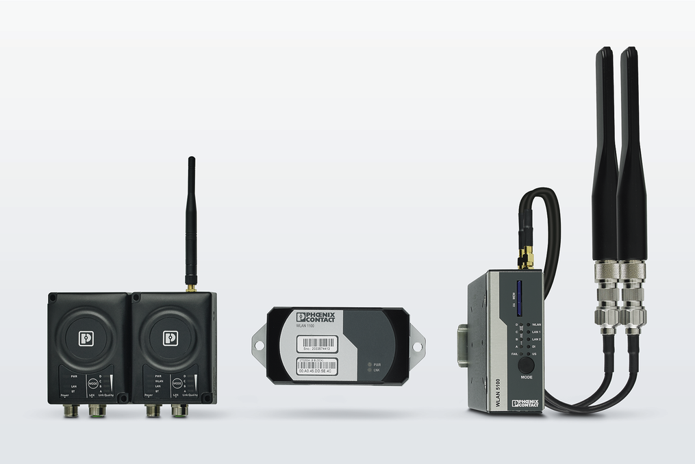
Over the last year, other than staring at four walls of the home office, we have seen a lot of retrofit projects come to us to help to bring older technology up to date. Most common needs are to replace serial systems with an ethernet based topology. The most common product family that comes up in applications is the FL WLAN 2100 and the FL WLAN 5110 to create a wireless cable replacement of what was the serial communication.
The most common application is retrofitting communications to overhead cranes. These faithful work horses play such a crucial role in everyday production that there is no leeway for a critical piece of equipment to be down due to component failure. A lot of maintenance departments spend thousands on spares that are depleting at an alarming rate due to obsolescence or the OEM that commissioned the crane originally simply does not exist anymore.
Most companies who decide to retrofit an overhead crane have already decided to gradually replace serial systems to ethernet. With a commitment of either an ethernet card placed on the PLC rack or replacing the PLC all together to a more modern unit. Once this has been decided, a simple network topology is created for testing purposes with cable runs to the control panels of the overhead cranes.
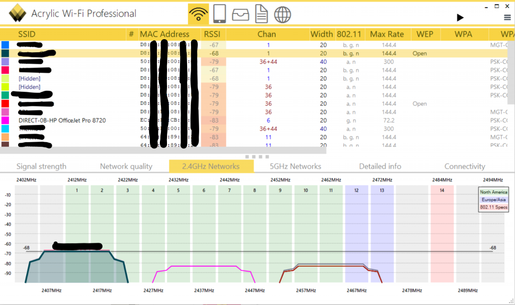
The product of choice is based on certain criteria and the environment they are situated in. In most cases the WLAN 2100 is a perfect product for most WLAN needs, but sometimes there needs to be a more complex solution to achieve the expectations of the customer. Range plays a big role in what product to choose, also WLAN airspace. If there are 5-6 WLAN networks already in place, these can cause issues. This is where Phoenix Contact can help in surveying and planning a WLAN network in an application.
For this application, I want to share with you what was a perfect example of a more complex WLAN setup and what can be possible.
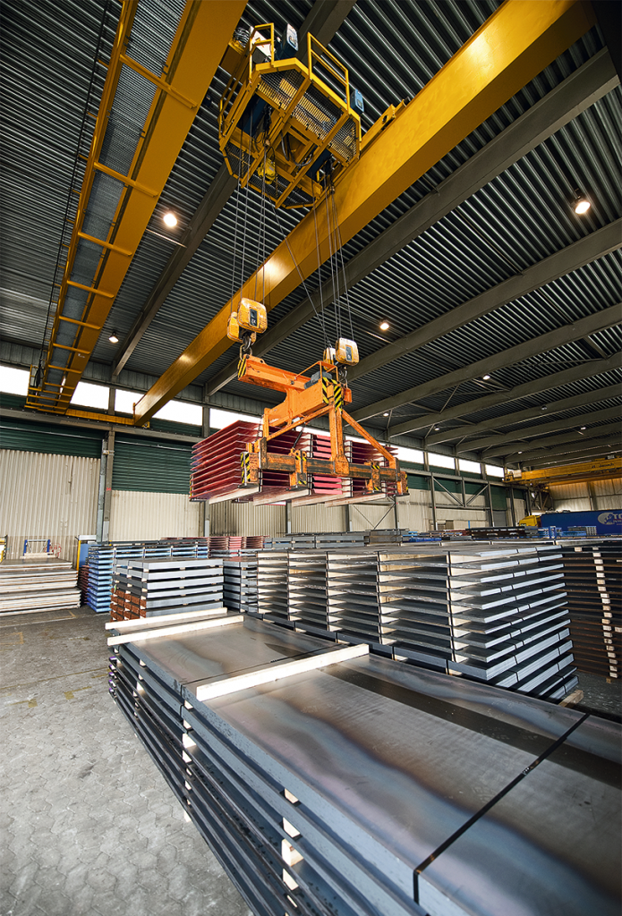
A customer had a serial based overhead crane, but was now really struggling to source spares for the crane and needed a more off the shelf solution to keep his production efficient and downtime to a minimum. The range required was a hall of 100 meters long with 2 cranes on the same crane track.
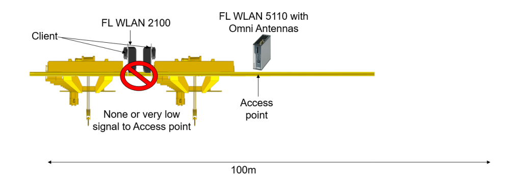
Pointing a single directional WLAN unit down the hall was not possible since the first crane would be blocking radio transmissions to the second crane. We could not use antennas that would be placed on top of the cranes to avoid the blocking issues due to roof trusses having a small clearance between the truss and crane body.
The customer had already had ideas of 1 access point in the 50-meter mark in the middle so both cranes that can be connected via a client device on the crane connected to the access point with Omni antennas. In a perfect world this would work, but in practice the customer would soon experience problems. If the cranes were to be close together at either end of the crane rail there is a high possibility that there would be very low signal, or no signal, due to the two huge chunks of steel beams blocking the signal to the access point.
To solve this issue we had to create a network within a network. I know what you’re thinking: WLAN INCEPTION! Advising the customer of the problems that are likely to occur in the solution proposed to us of a central Access Point, we proposed two networks that are independent but would still work on the Layer 2 structure of the network. The first network would be comprised of 1 FL WLAN 5110 (1043193) with two directional antennas that would handle the more extreme distance the cranes could travel 80/90 metres. This access point would be then configured to connect to a single client on network 1, in this case a WLAN 2100 (2702535)
An ethernet cable would then be plugged into the client from network 1 and plugged into the access point of network 2- another WLAN 2100. This unit can be configured to be either a client or an access point.
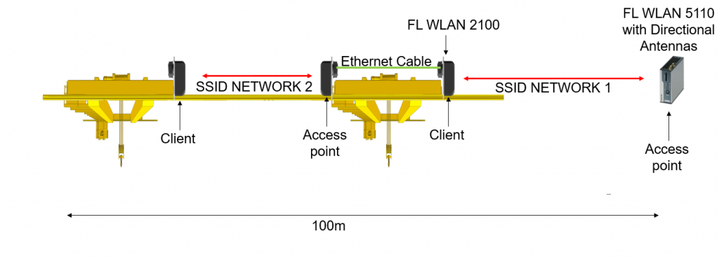
A third FL WLAN 2100 in client mode would be installed on crane two. This would create the bridge between crane 1 and crane 2. Traffic can then be passed over the network from one network to the other.
The setup of the two networks come with conditions; the two networks need to be on different channels to avoid conflicting with each other. Another condition is to lock the client to the channel set on the access point, if a client goes below a certain threshold of signal it will start to roam for a better signal. If you tell the client to work only on the channel set this will avoid this issue. The last condition is that the two networks are separately named, while each AP can be contacted via layer 2 communication a congested 2.4ghz airspace might be restrictive in its application. This is where you would look at the frequency (5Ghz)
The application solution provided by Phoenix Contact created a stable and strong link on these two moving cranes eliminating the environmental challenges presented to us.
If you would like to talk to Phoenix Contact regarding any network and wireless projects, contact Gareth on 07946 757375 or email gchamberlain@phoenixcontact.com